 With most projects, they have to start somewhere. One day I hope to make a foundry for melting and casting metal, and the logical place to start was the fire. After an amount of research and parent nagging the babington oil burner build was commenced... Here's the not very well documented build log for it.
--Edit--
For those that aren't familiar with the operating principle of a Babington oil burner, here's a brief overview. The design is very effective at reducing/eliminating clogging due from unfiltered oil as the oil never actually passes through the jet. It instead flows over the top of a small (or large, people have used door knobs) metal ball, creating a film over the surface. A jet in this ball is made for the air to pass through, which with a sufficient pressure behind it (usually 30PSI or lower) atomises the oil as it passes over the jet. This, combined with a small recirculation (and oil capture, as the oil naturally drips off the bottom of the ball) system forms a very reliable burner, with very few parts to clog up.
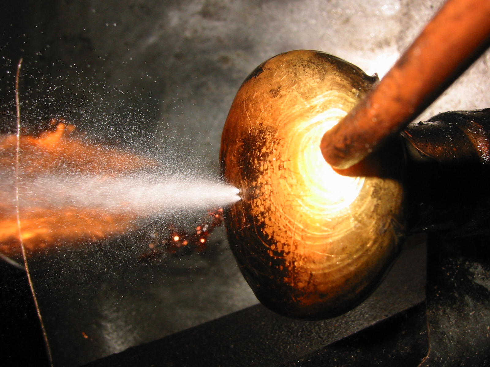
This image from AIP Engineering shows the atomisation extremely well. (see their very useful HowTO here)
--End edit--


For the air jet a small dome nut was chosen, placed on the end of a 8mm pipe which had a thread cut into it. For the jet itself a slightly larger than recommended hole of 0.45mm was used, as all the smaller ones on hand decided they weren't going to cooperate. The air line was centered by eye, adjusting the 6 set screws which are 120 apart, in two rows.
The oil feed over the ball was accomplished by the use of a 1/4 copper tube, which was beat into a shape where it would dump the oil on the ball, with a rectangular orifice at the end. This isn't as efficient as other designs where the oil is targeted straight to the jet itself by means of channels etc, but it works just fine.

The oil feed over the ball was accomplished by the use of a 1/4 copper tube, which was beat into a shape where it would dump the oil on the ball, with a rectangular orifice at the end. This isn't as efficient as other designs where the oil is targeted straight to the jet itself by means of channels etc, but it works just fine.

For the ignition two holes were drilled and tapped on either side of the tube to fit a pair of NGK BPR6EFS spark plugs, which had a majority of the thread cut off, leaving mainly the ceramic insulator. This was done to 1, allow for the arc to jump between the two plugs rather than to their shell, and 2, to stop the arc from having the temptation to jump to the thread rather than to the other. Spark plugs were used simply because an insulator/bushing was needed and my dad just happened to have changed the plugs in our car.
 As can be seen in this picture, the arc struggles with air passing by it from the jet, but it still manages to hold in there on 36V

For the test runs, these plugs were hooked up straight to the flyback and its ground, which can be slightly seen in the bottom picture (sorry, I got carried away with the fire to take many pictures). There are three 12V lead acid batteries feeding the ZVS driver, as 24V was not enough to keep the arc going with the air passing it, instead bumping it up to 36V.


If you have any suggestions or comments, drop a comment below, I'd love to hear from other makers!
Hi, nice post. Well what can I say is that these is an interesting and very informative topic. Thanks for sharing your ideas, its not just entertaining but also gives your reader knowledge. Good blogs style too, Cheers!
ReplyDelete- The oil burner service in ma